Getting Started
Hardware Setup
Connect the RH01T9k to an SPI controller and confirm the electrical and timing requirements before running a test.
Tang Nano 9K pinout
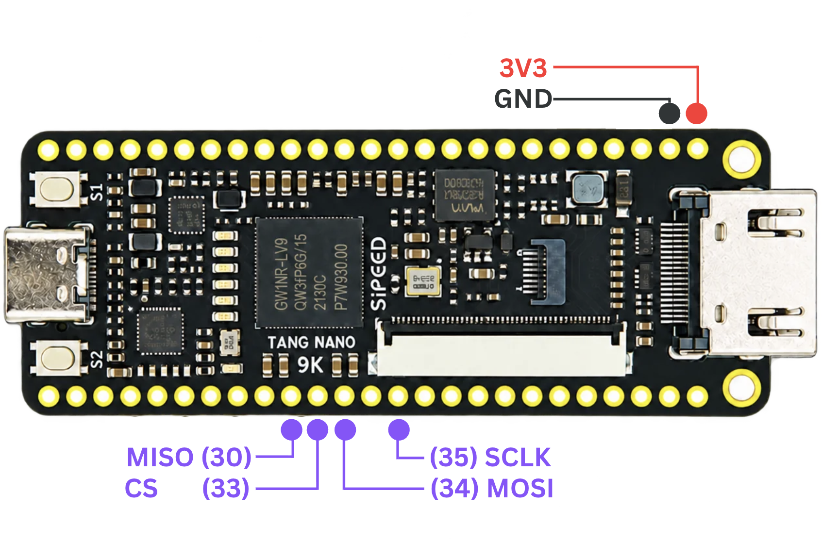
Electrical requirements
Use compatible 3.3 V logic levels between the SPI controller and RH01T9k.
Always connect a common ground between the controller and emulator board.
Caution: Do not connect incompatible I/O voltage levels directly to the emulator pins.
SPI operating requirements
Before running a test:
- Keep SCLK at or below 20 MHz.
- Configure the SPI controller and emulator for the same SPI mode.
- For SPI Modes 1 and 3, add a CS-to-SCLK setup delay before the first clock edge. One full SCLK period is a conservative setting.
- Keep CS low for the entire SPI transaction.
- Return CS high between transactions.
- Transfer a whole number of eight-bit bytes in each transaction.
Note: A continuously low chip select is treated as one continuous SPI transaction.
Serial control connection
The computer configures the RH01T9k through the USB serial control connection.
Keep the control-link baud rate at:
115200 baudThis baud rate is fixed and should not be changed.
Before starting a test
Confirm that:
- the SPI wiring is correct
- the SPI clock is within the supported range
- the USB serial connection is available
- no other serial program is using the board's port
Once the hardware is connected, continue to the Quick Start guide to verify communication with Python.